


Instructions and diagrams for re-wiring your Cafe Racer.
If you are planning on re-wiring your Cafe Racer and don’t know where to start, grab a seat.
Hopefully you’ve seen our post on what the electrical components do in your custom bike, or how to pick the right cafe racer parts. This article will show you step by step how to hook it all up and get your Café Racer or Bobber firing!
Things we will cover here:
- Parts you need
- Mounting your battery
- Charging/running circuit
- Lighting circuit
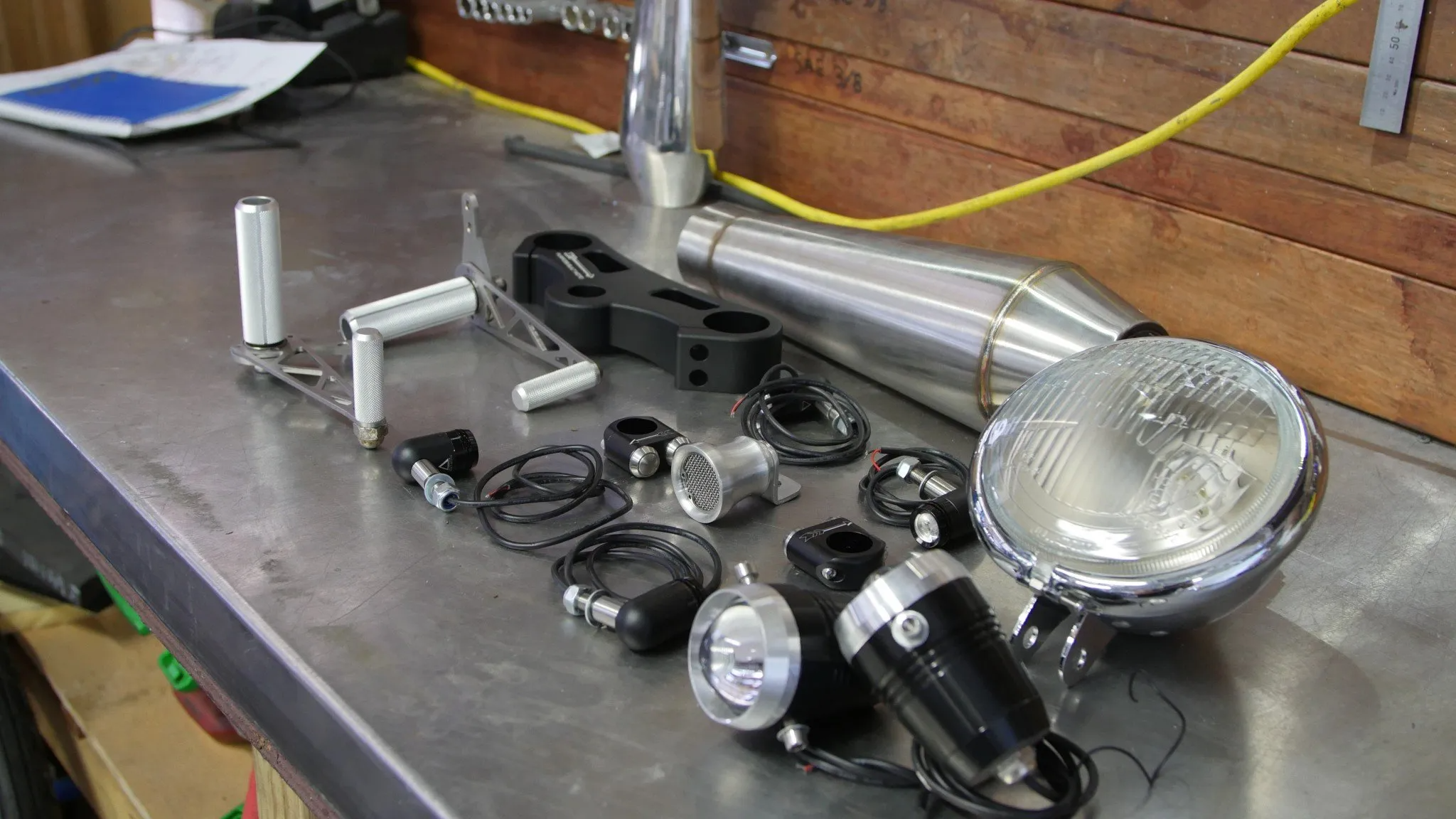
Parts you need
If you are still missing any of the parts for your build, make sure to check our custom pieces in our Online Shop.
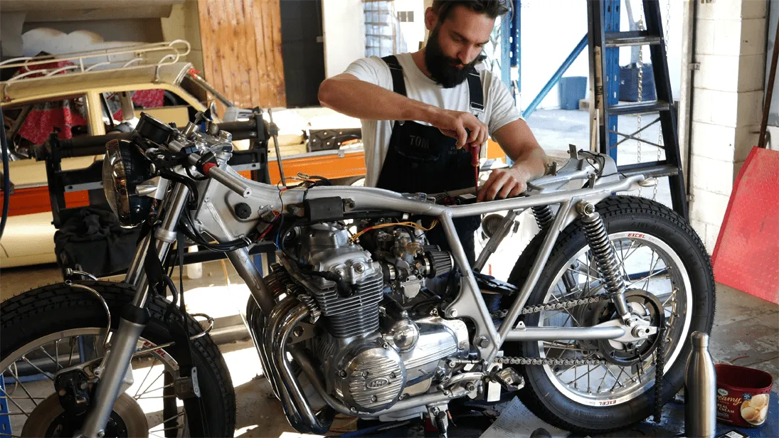
If you’ve read our “how to build a café racer” blog the wiring should be one of the final steps on your build. I like to split this job in 2, you have a running/ignition circuit and your accessories circuit, with 2 separate diagrams. This makes the drawings simpler and if anything goes wrong it’s easier to trace the problem.
Before you think about wiring, mount everything on your bike from coils to your lights and speedo.
Battery mounting
Start by mounting your battery, and figuring out where your electrics tray will go. That should house your
- starter relay
- Black Box Control Module
- CDI
- Flasher unit
- Fuses or circuit breakers
Once that’s sorted mount the Reg/Rec either underneath or next to the battery. It needs airflow as it gets warm, so try not to put it in a cramped spot that’s fully enclosed.
Now you’re ready to start wiring. Some people prefer to run 1 wire the length of the bike and tap off for the active wires. In my mind this way tends to lead to a lot of joins and if one wire has an issue, your bike is going to have big problems.
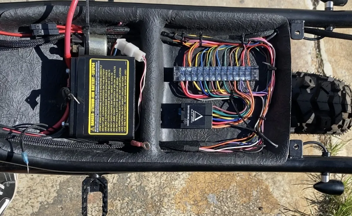
I like to use a Terminal strip and join all the positive wires in the electrics tray. I separate the terminals into sections:
- Switching
- Lights
- Charging circuit
Shown below is our latest Black Box control module with optional accessories kit that includes a terminal strip and 2 micro fuse holders.
Using these accessories in your wiring is the simplest and neatest way we’ve found to make sure your motorcycle electrics run reliably while simplifying the job so anyone can do it.
I also always draw my wiring diagram, but I’m good with electrics so use mine to save you some time!
Get the PDF’s here: Wiring Diagram Download
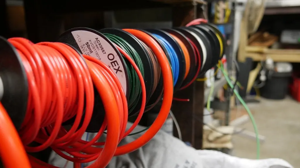
Before you get going re-wiring your cafe racer, make sure you use quality connectors or solder joints and heat shrink your connections. With that done, let’s start with the charging/running circuit.
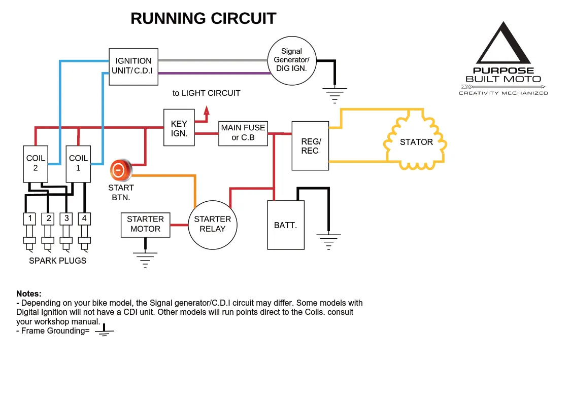
Charging/Running Circuit
- Run a black lead from your battery –ve to a clean bare metal part of the frame and bolt it on, this turns your whole frame into a ground. Also be sure to ground your engine/gearbox case at one point. Then run a red from the +ve to the starter coil. Connect the other side of your starter coil to the starter motor. This is done in heavy duty wire.
- Run a standard red 15A cable to the main fuse (20-30A) then to your key ignition. From the key ignition there will be 2 other cables; one goes to your charging circuit and coils, the other to a fuse for the lighting and accessories circuit (10-15A).
- Start finishing up your Running circuit, connect the 3 (normally yellow) wires from the stator to the reg/rec then connect the red to the battery +ve and the green to the –ve. Some bikes (Honda CB750s) will have extra cables to connect from the reg/rec to the coils. If not it will be included in the signal generator and CDI unit.
- Get your signal generator and CDI unit plugged in (or points), then run your blue coil trigger cables and connect the coils to your spark plugs.
Quick side note – if you would like to know more about motorcycle wiring diagrams, check out this article by bikezombies
That’s your charging and running circuit sorted, (the easy part) now work on finishing your lights and accessories. They’re already mounted up so the looming and connection is all that’s left.
Lighting Circuit
- You’ll have to run wires from your electrics tray to the front of the bike. I use a Black “snake skin” cable sleeving to protect my wiring from damage and it looks a lot better than your standard plastic wrap or electrical tape. as a minimum you’ll need;
Accessories
- 1 red active linked to the gauges, horn and brake switch
- 1 black ground wire
- 1 Purple for front brake switch
- Signal Lights depending on your gauges ( Neutral, Oil, Engine)
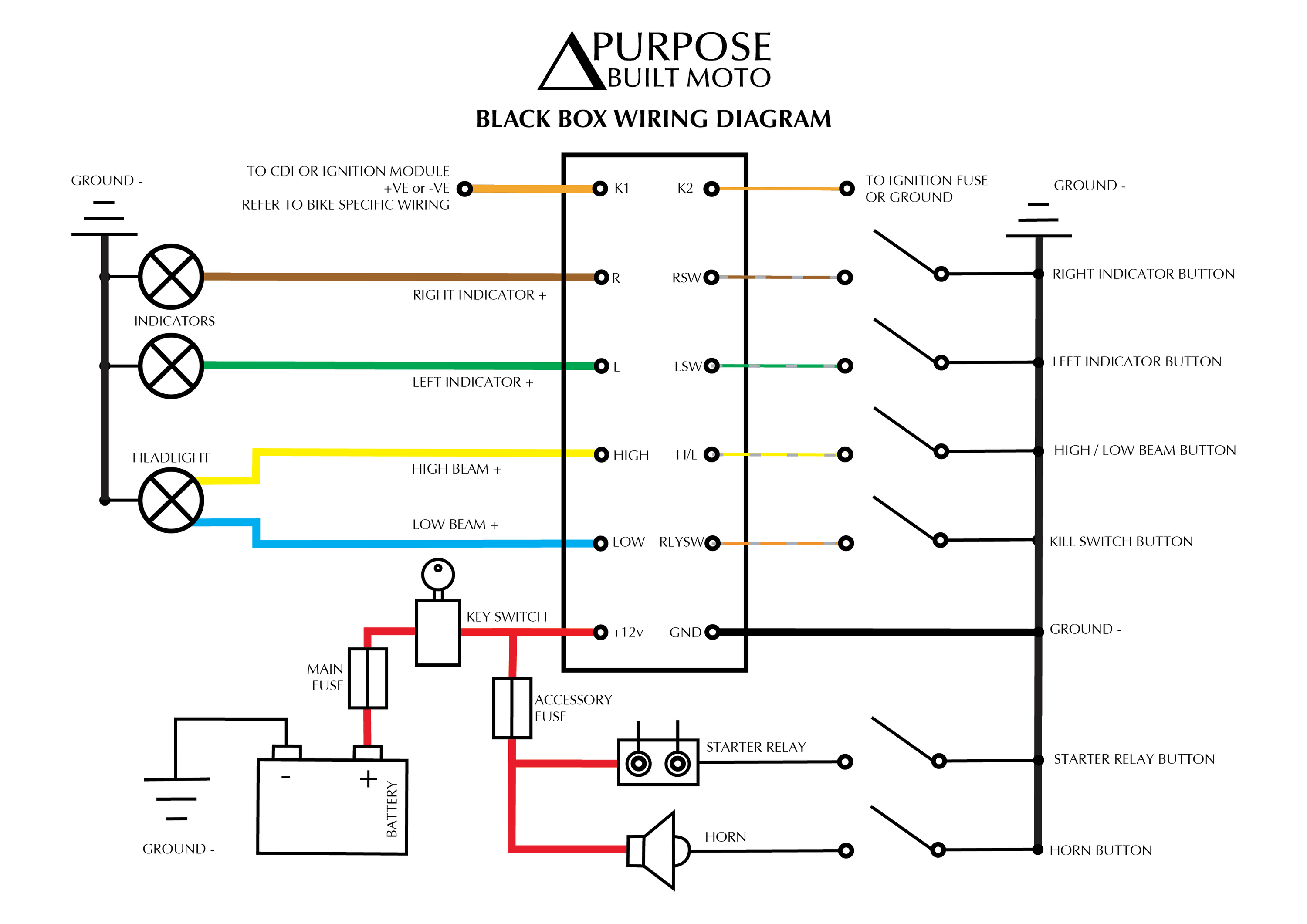
Lights
- 1 Blue for Low Beam
- 1 Yellow for High Beam
- 1 Green for Left turn
- 1 Brown for Right Turn
- Lights can be Grounded to the frame
Left Switch
- 1 green wire for rear left indicator
- 1 orange wire for the Horn
- 1 blue wire for high/low beam function
- All switches switch to Ground (black wire)
Right switch
- 1 brown wire for right indicator
- 1 yellow wire for the Kill switch
- 1 pink Wire for the Starter Coil (optional)
- All switches switch to Ground (black wire)
- Try to use solder connections on wire joins and good quality joiners for connection to switches and lights.
- Wire all buttons and install into switch housings, for in depth info on this check out our momentary switch guide
- Connect the headlight, and turn signals using the colours described above
- Connect your accessories +ve (gauges, brake switch, horn)
- Connect the other accessories wires as described above
- Connect any Dash lights relevant to your bike.
- All of your accessories will need to have the black wires grounded. You can connect this to the frame at any point or join them all and run a wire back to the electrics tray.
- With the cables connected, loom them into the cable sheathing and run them back to the electrics tray. Avoiding contact with hot areas or sharp edges.
- Now work from the rear of the bike back to the electrics tray (use snake skin here again). You’ll need:
- 1 red active wire for the rear brake switch, the running light, and the number plate light.
- 1 Purple switch wire from the brake switch
- 1 red wire for your brake light
- 1 green wire for rear left indicator
- 1 brown wire for rear right indicator
- 1 black earth wire
- The final step is to use your terminal strip to connect your wiring into the Black Box and linking the Horn and Brake lights up to their respective switches. The Gauges, Horn and Brake are run from a separate “accessories fuse” that’s not connected to the black box.
Now fire it up! I know there are simpler ways to wire a bike however in my experience, a little extra work here can save you heart ache if there is ever a problem. Simple fault finding is what I aim for.
I hope you’ve taken some good info away from this, again click here to download the PDF wiring diagrams I use for your own custom Café Racer, Bobber or Chopper project. Please leave me your comments below!
Thanks for taking the time and congratulations on completing re-wiring your cafe racer.
Tom.
John Doe
Purpose Built Moto is home for unique custom motorcycle builds. We offer a unique motorcycle customizing experience in the heart of the Gold Coast.


60 comments
Hey Alexandro,
That is the Black Box control module, it makes our button switches easily control you motorcycles functions.
you can check it out here: https://purposebuiltmoto.com/product/black-box-v2-lighting-control-module/
Amazing post! For the first time i’m starting to understando how motorcycle eletrics works! English isn’t my native languege, sorry, could you explain whats that board between the Terminal strips on the picture?
Hey Tom,
No doubt that is great writing, your article very informative and interesting. I have gone through entirely and each word, I appreciate your points of view. You’ve done a great job with making this clear enough for anyone to understand. Sometimes I was thinking to get over, but due to a heavy working schedule, I can not.
By the way, this has broadened my knowledge. Thanks for sharing.
Hey Jason,
The starter motor I always use a relay, but the kill switch and headlight I dont.
2 reasons. All my bikes run LED lights with low amp draw and generally they run a black box module that has in built relays to handle that load.
Hope that helps man!
Tom
Tom,
In neither your charging circuit, nor the lighting circuit do you show a relay for the starter, or the headlight.
I am finishing wiring my bike now, and it has been proposed to me that I MUST use these relays, though I am not sure I do. The argument being made is the massive electrical pull of the headlight, and starter will over amp the headlight switch and kill switch.
I dont have much room for them, nor do I want to invest the additional time / money unless absolutely necessary.
What are your thoughts?
Nice Post
Completely agree – blinking lights in adverse conditions are difficult to judge distance with. Which is why I always run two different light styles in such conditions. blink for attention, and steady state for distance judgement and also potentially “to see with” depending on the route.