
Planning to re-wire your Cafe Racer and unsure where to start? Grab a seat! This comprehensive guide will walk you through the process step-by-step, ensuring your Cafe Racer or Bobber is up and running in no time.
Understanding the Basics
Electrical Components:
- Stator: Generates power by rotating a magnetic component around a wire-wound basket.
- Regulator/Rectifier: Converts AC charge from the stator to DC to charge your battery.
- Ignition Switch: Controls power distribution to your bike's electrical components.
- CDI (Capacitive Discharge Ignition): Stores and releases a charge to the coils for ignition.
- Coils: Amplify the signal from the CDI to fire the spark plugs.
- Starter Relay and Motor: The relay controls high current to the starter motor, which starts the engine.
- Control Relay: Controls all of your bikes flasher and auxiliary functions
- Indicator Flasher Relay: (if not using a control relay) Controls the timing of your turn signals.
Introduction: Setting The Stage
Before jumpng into the wiring, make sure you’ve checked out our other posts on the electrical components in custom bikes and how to pick the right Cafe Racer parts. This article will cover:
- Necessary Parts and Options
- Battery Mounting Locations
- Charging/Running Circuits
- Auxiliary Lighting Circuit
Essential Parts And Tools For Re-Wiring
First, ensure you have all the necessary parts for your build. If you’re missing anything, check out our our Online Shop.
Wiring should be one of the final steps in your build, split it into two main circuits:
- the running/ignition circuit
- the accessories circuit
Draw up separate diagrams for simplicity and easier troubleshooting.
For Tools:
- Soldering Iron
- Cutter Pliers
- Wire Strippers
- Wire Shrink Wrap
- Socket Set
- Spanner Set
- Zip Ties
- Braided Loom Sleeve
The parts you need will be bike specific, but in basic the concepts are the same.
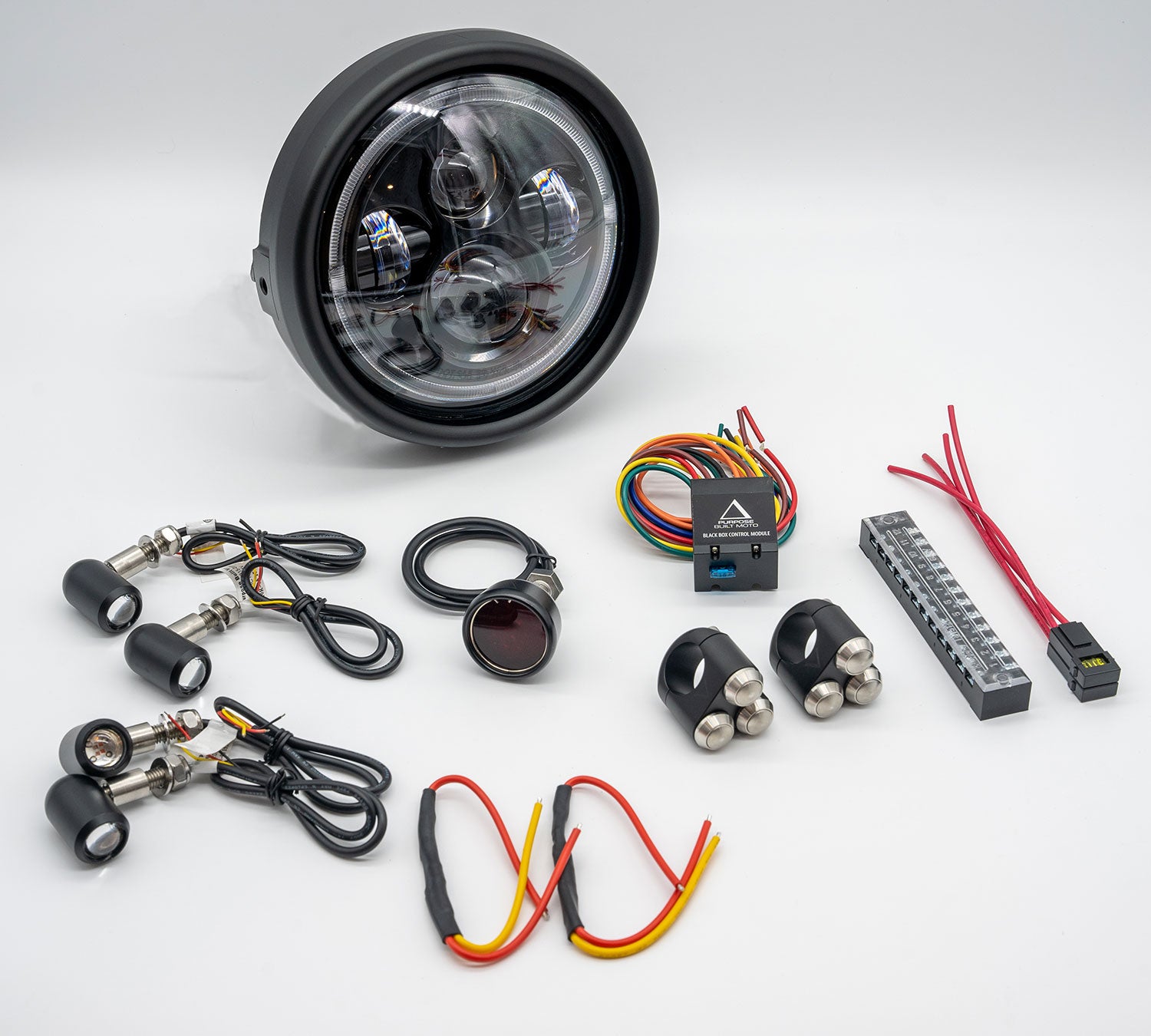
- Battery
- Control Relay or Flashers
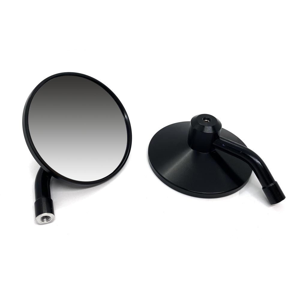
- Headlight
- Indicators
- Tail Light
- Plate Light
- Splitters or Resistors
- Speedo
- Coils
- Different Colors Of Wire
- Switches
These are just the basics, there will be some parts that are bike specific, for the purpose of this guide we'll keep it simple.
If you are doing a full rewire of your bike consider having a look at our complete build kits.

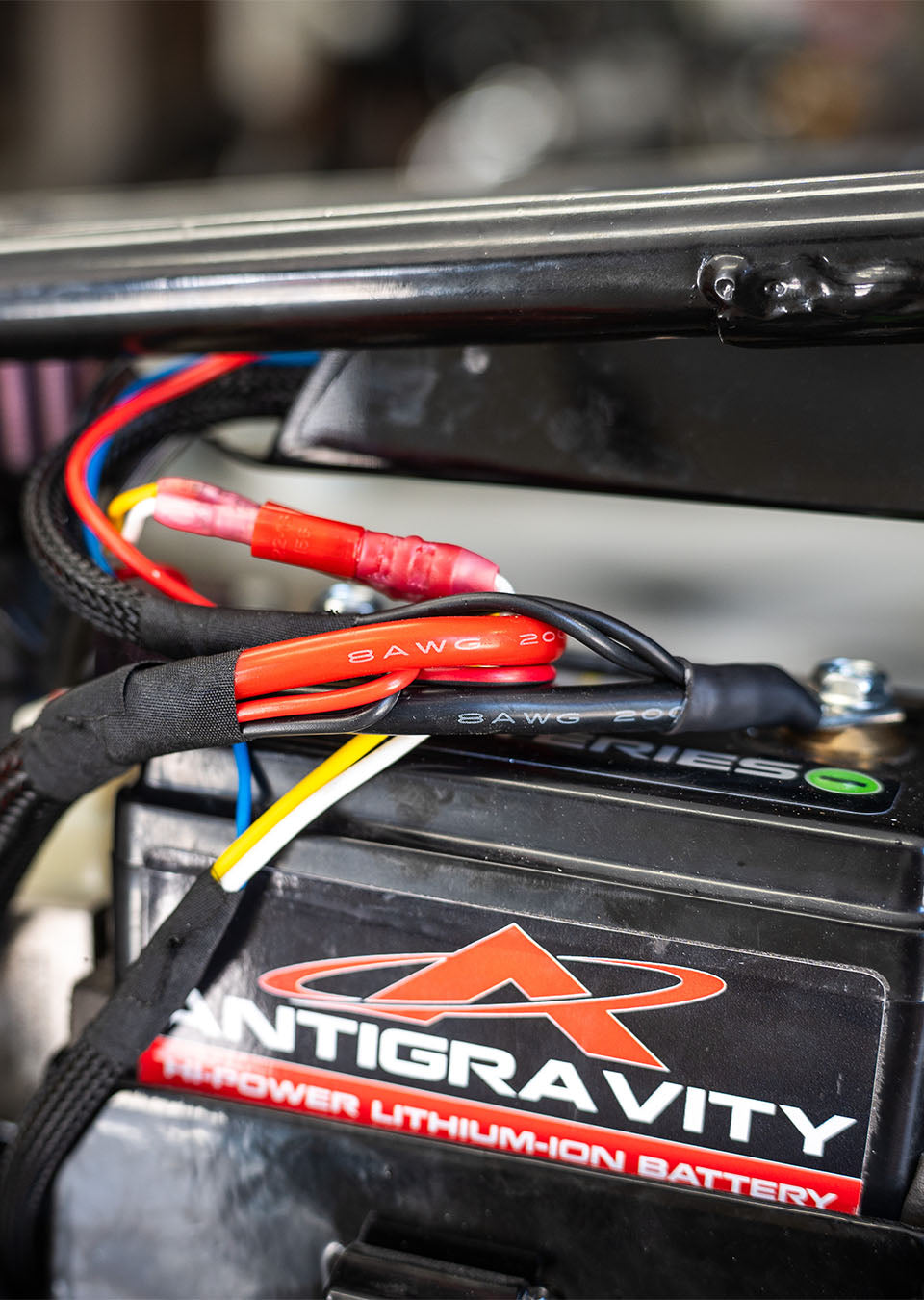
Mounting and Planning
Begin by installing your battery and deciding on the placement of your electrics tray. Organise your bikes main electrical components:
- Starter relay
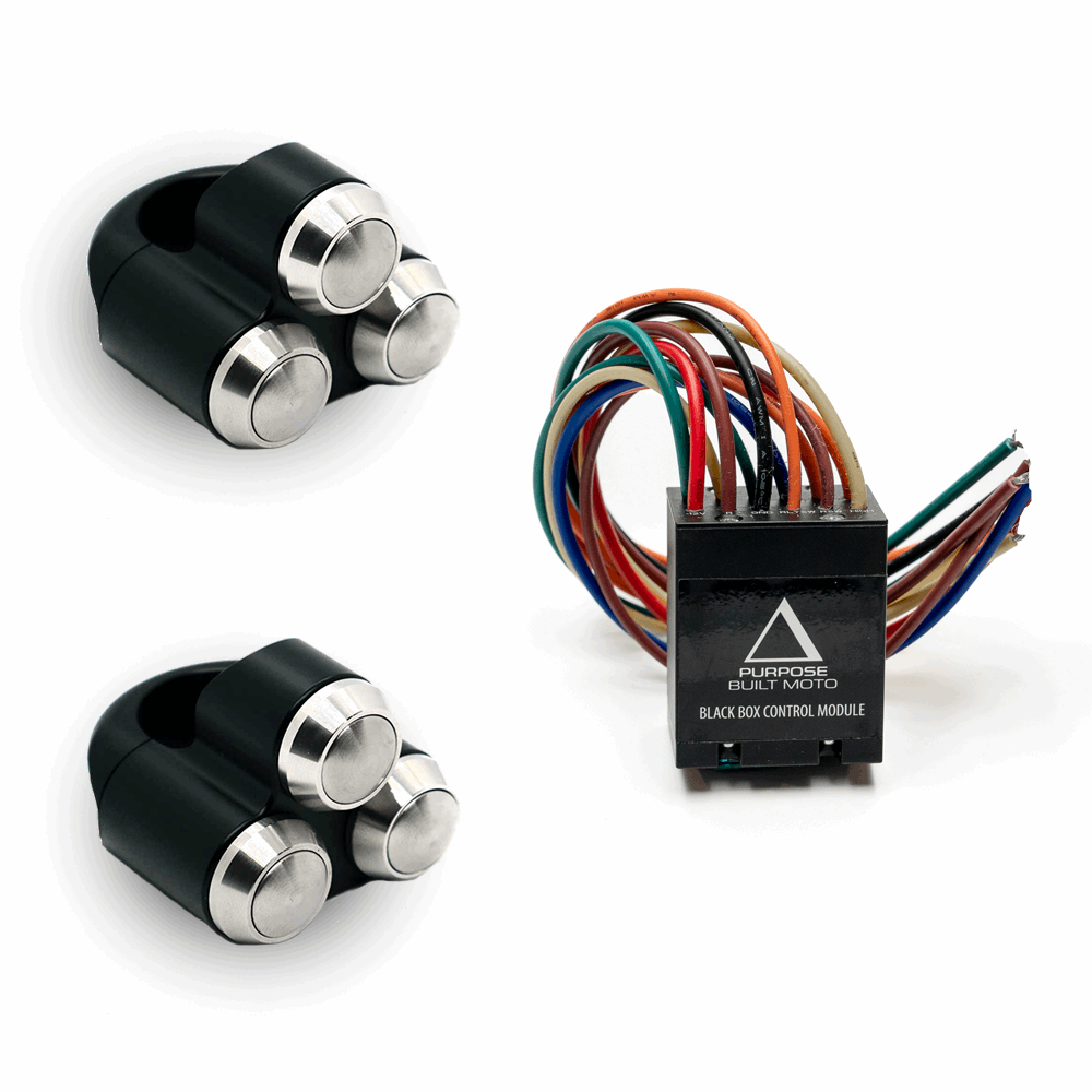
- Black Box Control Module
- CDI unit
- Flasher relay
- Fuses or circuit breakers
Make sure that the electrics tray is easily accessible and has enough space to organize these parts neatly. Once positioned, mount the regulator/rectifier (Reg/Rec) close to the battery, either underneath or adjacent to it.
(Note) The Reg/Rec needs proper airflow to avoid overheating, so avoid placing it in confined, poorly ventilated areas.
Wiring Setup
With the main parts mounted, you can now start the wiring process.
Some builders prefer to run a single wire the length of the bike and tap off for individual connections. However, this method can lead to numerous joints, increasing the risk of electrical issues if one wire fails.
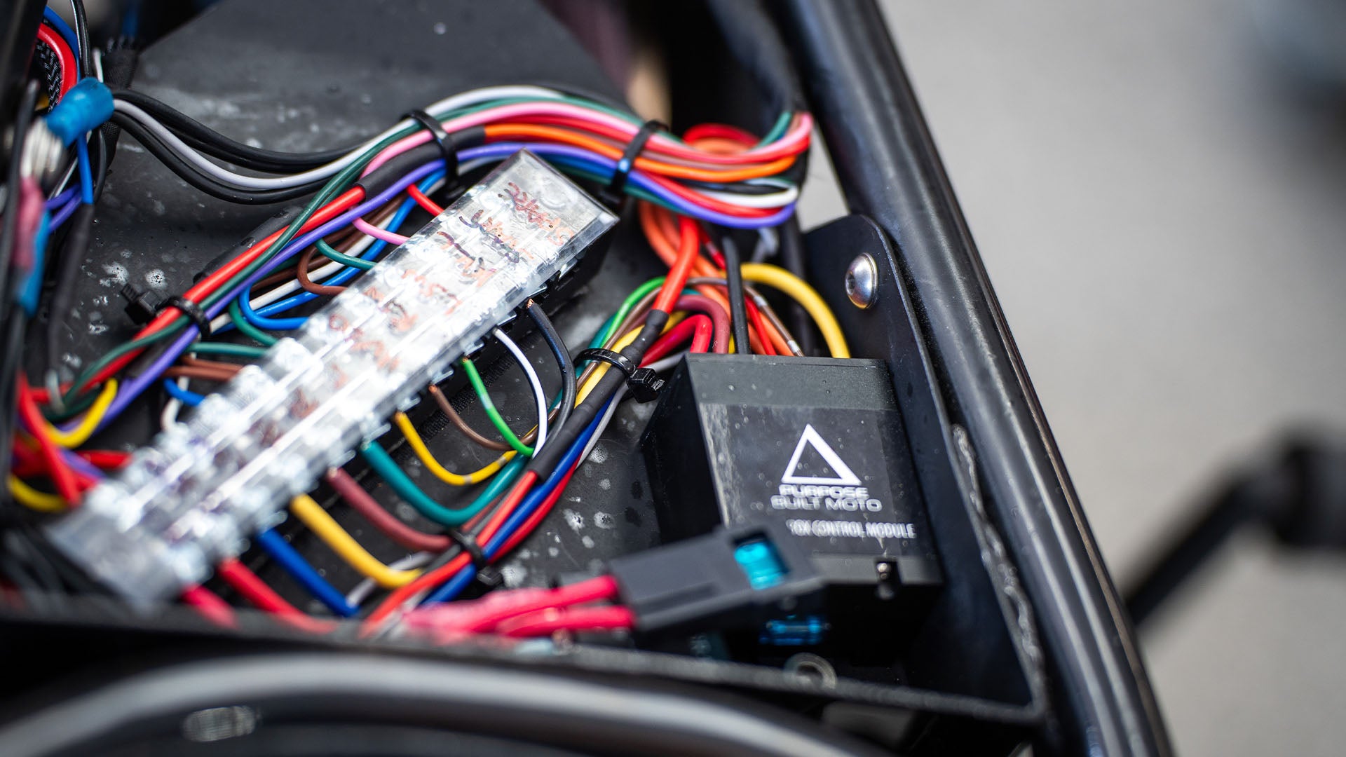
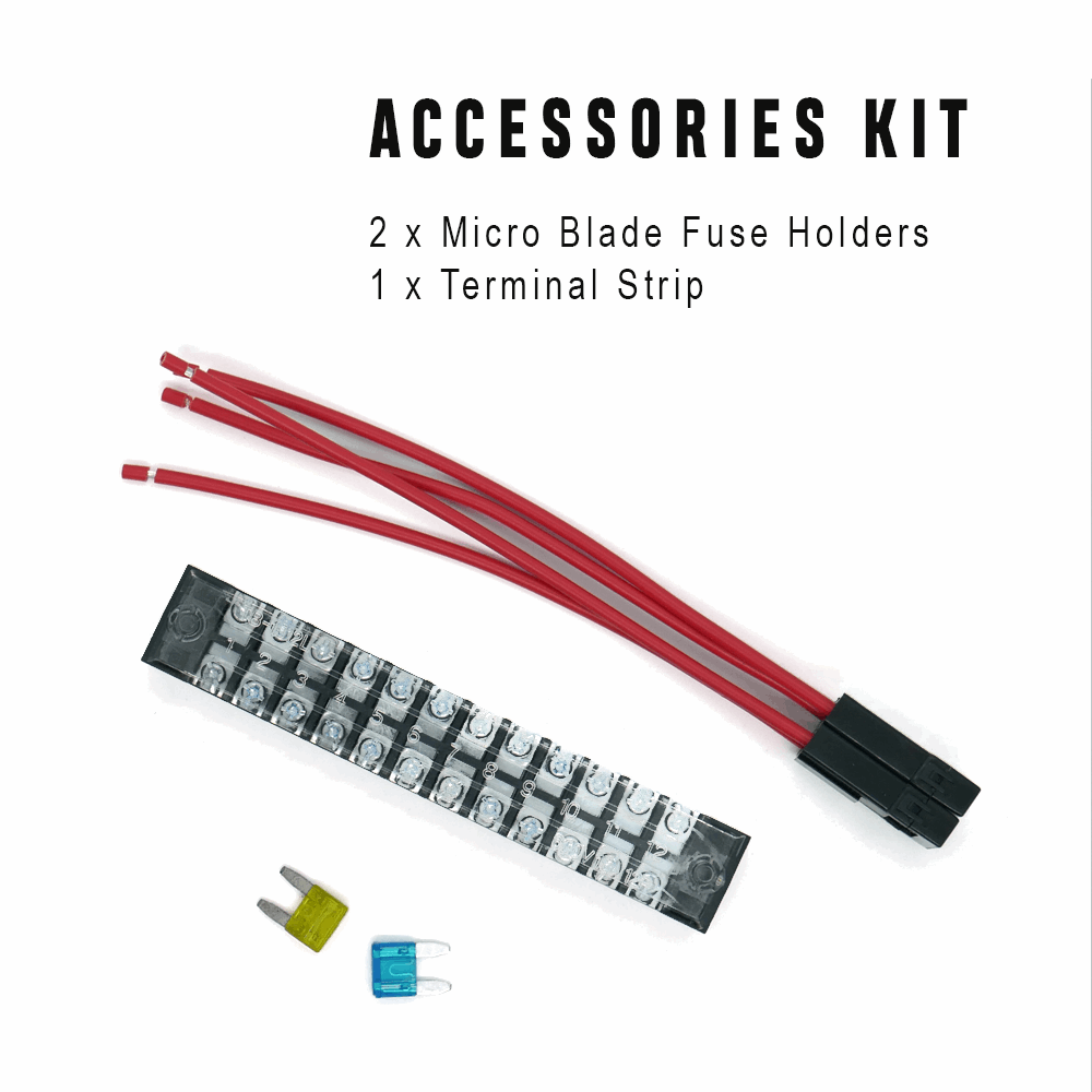
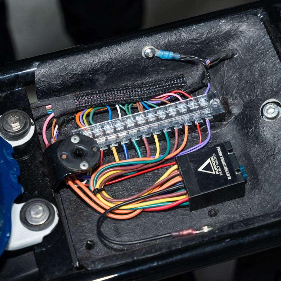
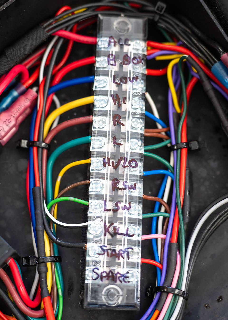
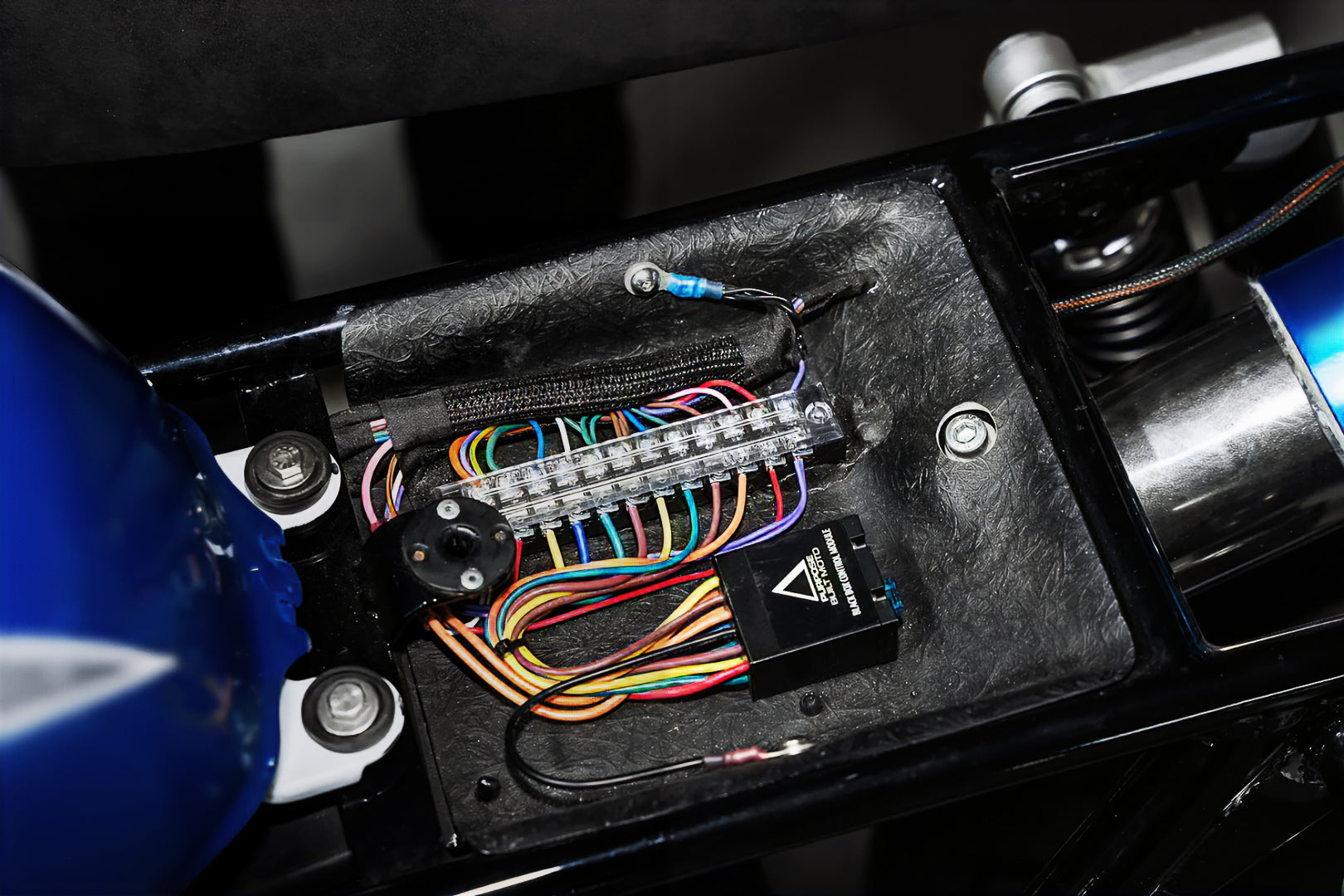
A more organized approach involves using a terminal strip like what we have in the blackbox accessory kit to manage all positive connections within the electrics tray. Separate the terminals into sections for:
- Switching
- Lights
- Charging circuit
This method helps in keeping the wiring neat and troubleshooting easier. Our latest Black Box Control Module comes with an optional accessories kit, which includes a terminal strip and two micro fuse holders. Using these accessories simplifies the wiring process, ensuring reliable performance and an easier setup, even for those new to motorcycle electrics.
Charging/Running Circuit
- Grounding: Run a black lead from your battery’s negative terminal to a clean, bare metal part of the frame and bolt it on, turning your whole frame into a ground. Ground your engine/gearbox case at one point.
- Connecting the Starter: Run a red cable from the positive terminal to the starter coil, then from the starter coil to the starter motor using heavy-duty wire.
- Main Fuse: Run a standard red 15A cable to the main fuse (20-30A) and then to your key ignition. From the ignition, run one cable to the charging circuit and coils, and another to a fuse for the lighting and accessories circuit (10-15A).
- Reg/Rec Connection: Connect the stator wires (usually yellow) to the Reg/Rec, then connect the red wire to the battery’s positive terminal and the green wire to the negative terminal.
- Ignition System: Connect your signal generator and CDI unit (or points), and run blue coil trigger cables to the coils, connecting them to your spark plugs.
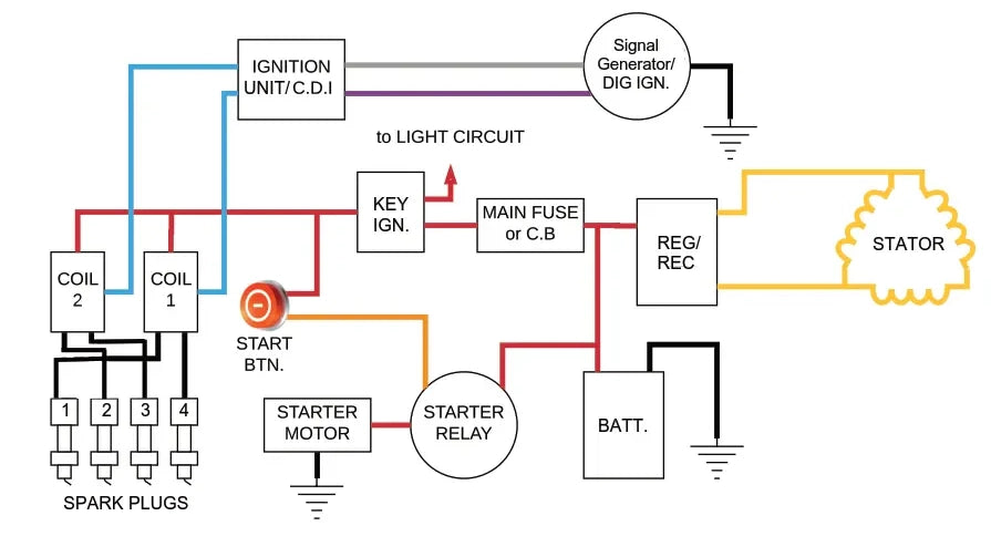
Depending on your bike model, the signal generator or CDI circuit may vary from the general description. Some models with digital ignition systems might not include a CDI unit and will instead connect directly to the coils. For specific details regarding your motorcycle's wiring setup, always refer to your workshop manual.
Quick side note—if you're looking to understand more about motorcycle wiring diagrams, check out this informative article by Bike Zombies.
With your charging and running circuit sorted (the easy part), you can now focus on completing the lights and accessories. Since these components are already mounted, all that remains is the looming and connecting of the wires.
Running Wires from the Electrics Tray to the Front of the Bike
To start, you'll need to run wires from your electrics tray to the front of the motorcycle. I recommend using black "snake skin" cable sleeving to protect the wiring. This not only safeguards the wires from damage but also provides a cleaner, more professional appearance compared to standard plastic wrap or electrical tape.
Accessories:
- Red Active Wire: Connect this to the gauges, horn, and brake switch.
- Black Ground Wire: Ensure a reliable ground connection for all accessories.
- Purple Wire: Use this for the front brake switch.
- Signal Lights: Depending on your gauges, include wires for Neutral, Oil, and Engine indicators.
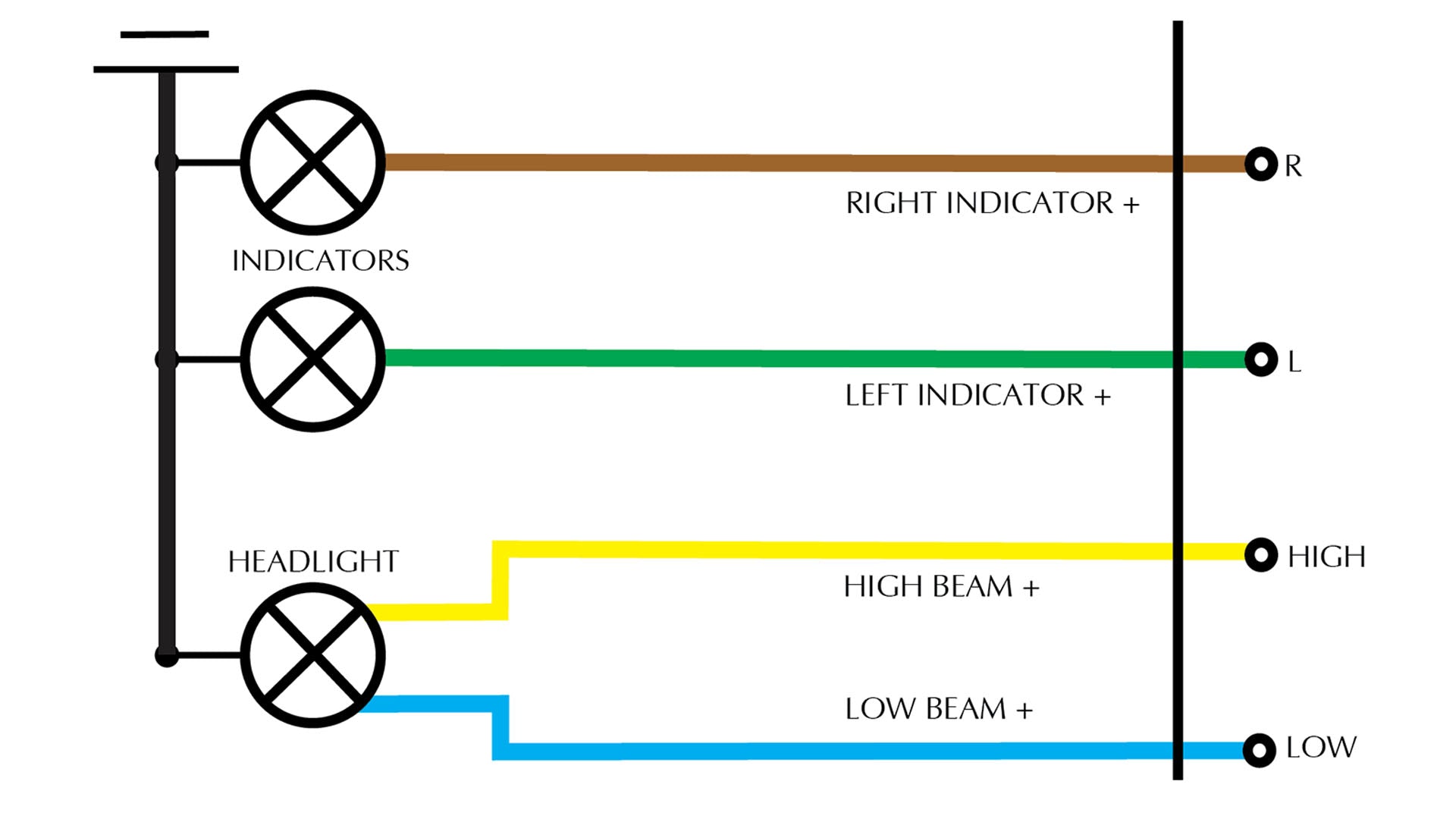
Lighting:
- Blue Wire: For the low beam.
- Yellow Wire: For the high beam.
- Green Wire: For the left turn signal.
- Brown Wire: For the right turn signal.
- Grounding: Lights can be grounded to the frame.
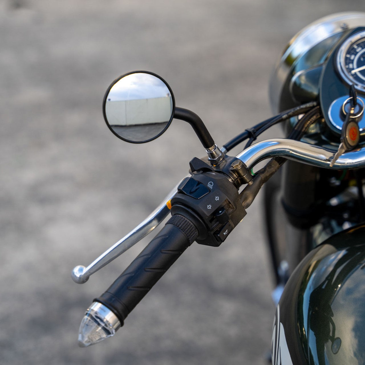
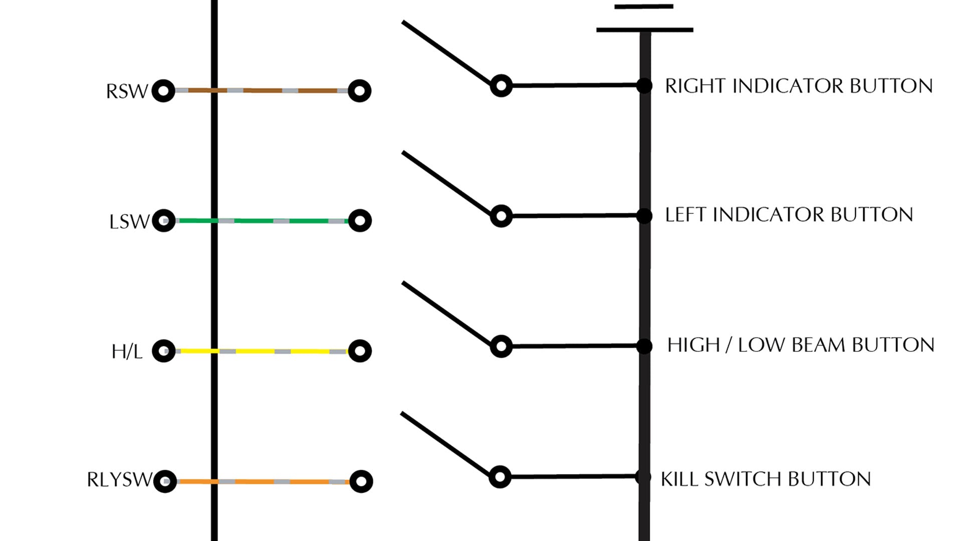
Left Switch:
- Green Wire: For the rear left indicator.
- Orange Wire: For the horn.
- Blue Wire: For high/low beam function.
- All switches should switch to ground using a black wire.
Right Switch:
- Brown Wire: For the right indicator.
- Yellow Wire: For the kill switch.
- Pink Wire: For the starter coil (optional).
- All switches should switch to ground using a black wire.
Use solder connections for wire joins and high-quality connectors for switch and light connections. This ensures durability and reliability. Wire all buttons and install them into switch housings; for detailed guidance, refer to our momentary switch guide. Connect the headlight and turn signals using the colors mentioned above.
Connecting Accessories:
- Connect the positive wire (+ve) for accessories such as gauges, brake switch, and horn.
- Follow the wiring descriptions above for connecting other accessory wires.
- Connect any dash lights that are relevant to your bike model.
- Ground all accessories' black wires to the frame or run a wire back to the electrics tray.
With the cables connected, organize them into the cable sheathing and route them back to the electrics tray. Ensure the wires are kept away from hot areas or sharp edges to prevent damage.
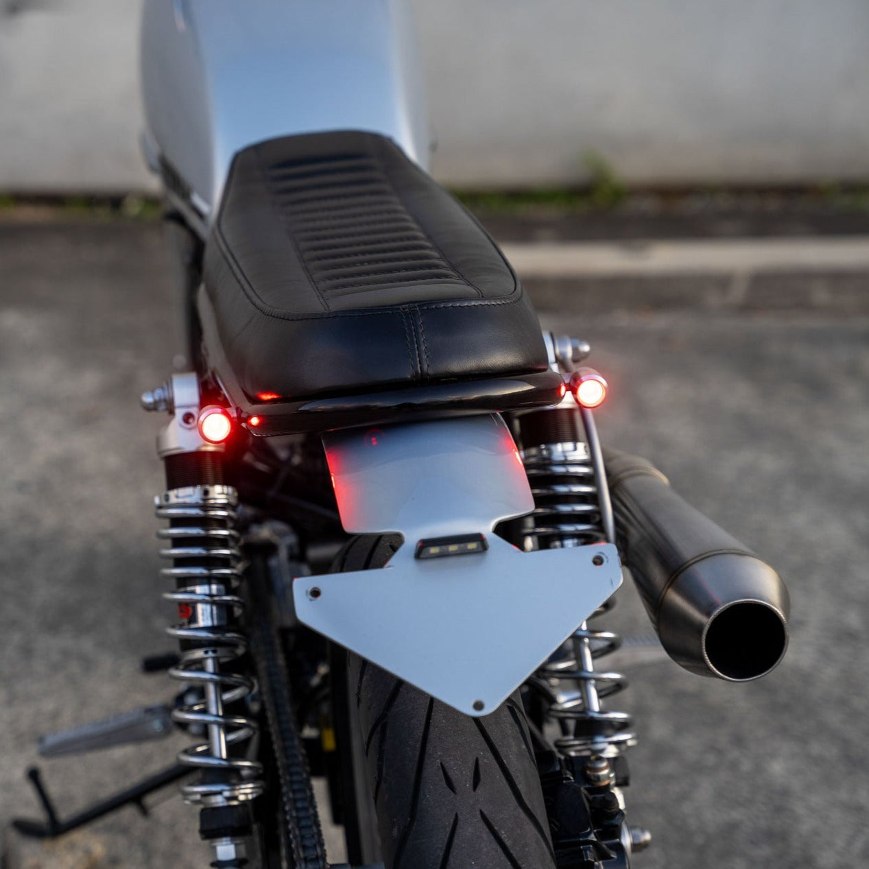
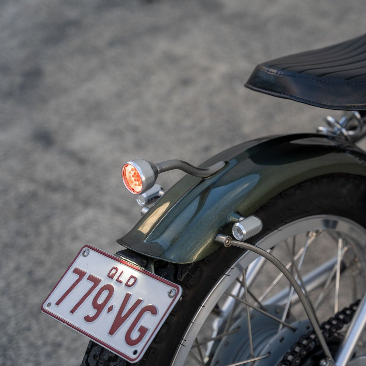
Running Wires from the Rear to the Electrics Tray
When wiring your motorcycle, start from the rear and work your way back to the electrics tray. Use "snake skin" cable sleeving to protect the wires and keep things tidy. You'll need:
- Red Active Wire: Connect this to the rear brake switch, running light, and number plate light.
- Purple Switch Wire: Run this from the brake switch.
- Red Wire: For the brake light.
- Green Wire: For the rear left indicator.
- Brown Wire: For the rear right indicator.
- Black Earth Wire: Ensure all components are properly grounded.
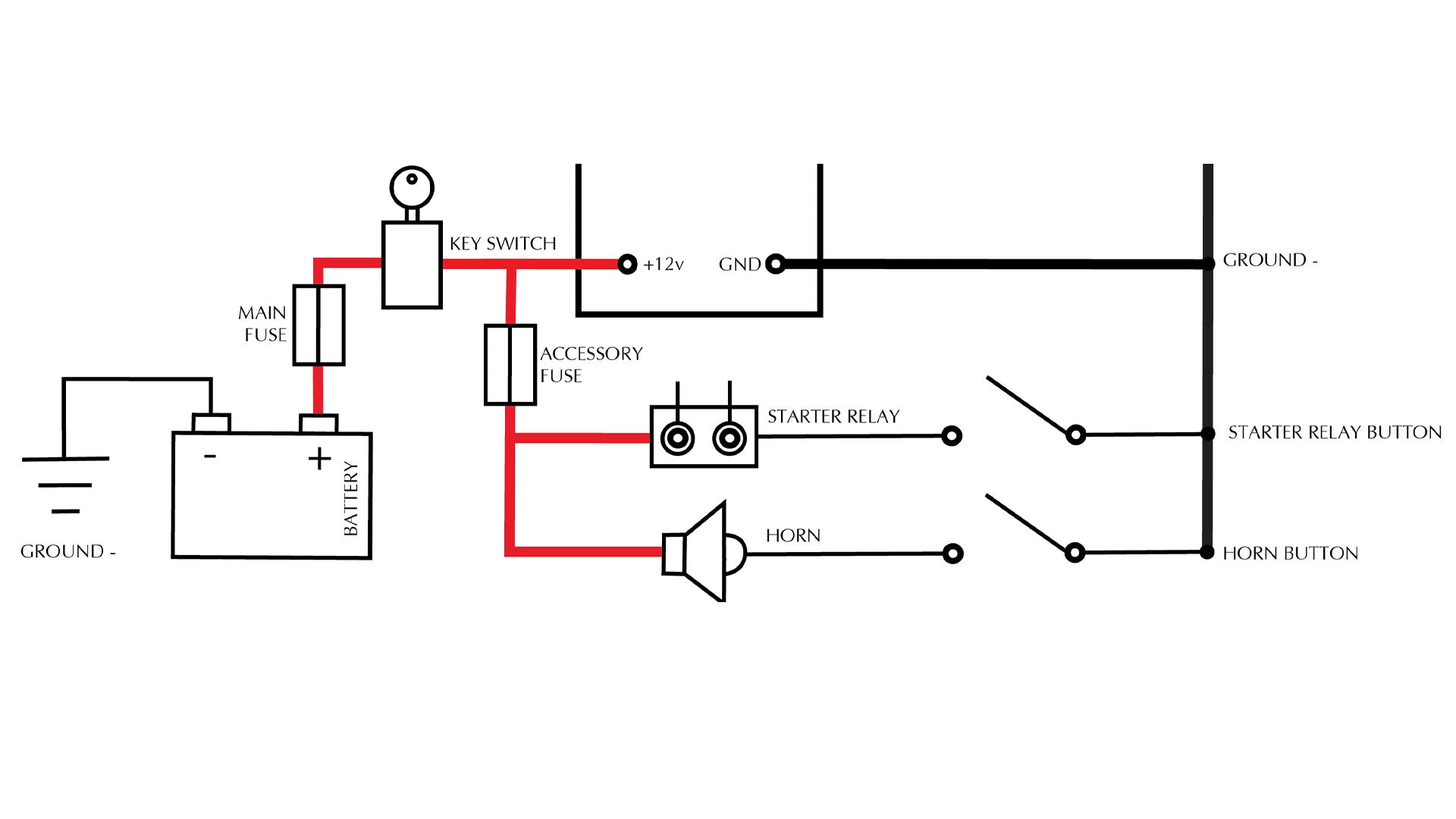
The final step is to use a terminal strip to connect your wiring into the Black Box, linking the horn and brake lights to their respective switches. The gauges, horn, and brake lights should run from a separate “accessories fuse” not connected to the Black Box.
Final Steps: Connecting and Testing
- Rear Wiring: From the rear of the bike to the electrics tray, run:
- 1 red active wire for the rear brake switch, running light, and number plate light.
- 1 purple switch wire from the brake switch.
- 1 red wire for your brake light.
- 1 green wire for rear left indicator.
- 1 brown wire for rear right indicator.
- 1 black earth wire.
- Terminal Strip: Use the terminal strip to connect your wiring to the Black Box, linking the horn and brake lights to their respective switches.
- Testing: Fire up your bike! Thoroughly check for any issues and ensure everything is functioning correctly.
Re-wiring your Cafe Racer might seem daunting, but with the right approach and tools, it can be straightforward. Download our PDF wiring diagrams for your custom Café Racer, Bobber, or Chopper project, and leave your comments below with any tips or feedback!
Final Thoughts
I hope this guide has been helpful. Congratulations on completing the re-wiring of your Cafe Racer!
Tom.
WE BUILD BIKES WITH PURPOSE.
Purpose Built Moto is home for unique custom motorcycle builds. We offer a unique motorcycle customizing experience in the heart of the Gold Coast.


